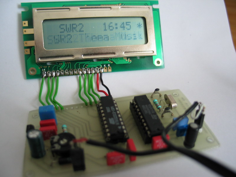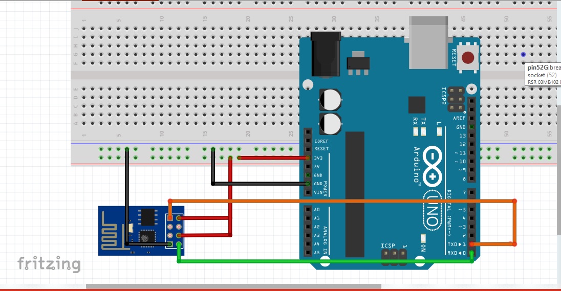
LCM1602 will be responsible for converting I2C data to LCD data and control signals. For example, say you want LCD pin D7 to connect.

Just put the Arduino pin numbers inside the parentheses in this order: LiquidCrystal(RS, E, D4, D5, D6, D7) RS, E, D4, D5, D6, D7 are the LCD pins. You can use any of the Arduino’s digital pins to control the LCD. By using this way, ESP32 will only use 2 GPIO pins which act as I2C SDA and SCL pins. The LiquidCrystal() function sets the pins the Arduino uses to connect to the LCD. Both programs do not require any external libraries or hidden code and I believe more flexible. Program At90S2313 With Arduino Lcd Display Code And Try As usual, I will do a breakdown of the code and try to explain some of the concepts within it that may be difficult to understand. See Interface I2C LCD to Raspberry Pi in C. When you configured the second, slave I2C Arduino you gave it a unique address? Is that address the one you're using to get the data via I2C or have you used some default address that is the same as the LCD (which would probably confuse it)? This is an Arduino version of my Raspberry Pi program. Arduino library supported, use a line of code to complete the display. 20 MyLCD Firmware: // MyLCD.c / Two port, 8 BIT LCD control program Writen. Only 2 Arduino pins are occupied (Use I2C interface). The interface is controlled with an Atmel ATtiny2313 AVR microcontroller. Through the bitmap convert software you can put your favorite picture displayed on I2C_LCD, without the need for complex programming.

Program At90s2313 With Arduino Lcd I2c Driver Module 1: Lights and LEDs In this module you’ll build several projects using lights: LEDs, lamps and RGB LED strips.


 0 kommentar(er)
